 The best way to trouble shoot your hexagonal beam is to do it on the ground before raising it onto the mast or tower.
Many new hex owners in their enthusiasm to get the beam on the air leave out the simple tests that should be done before it has been installed on the mast/tower. And then when they get it up on the mast or tower and things don’t work as they should, the first thought is, “Something is wrong with my hex beam!” But in fact, that is very seldom the case. Our experience is that 95% of the problems experienced by users ultimately turn out to be in the feed line or equipment, or even the test equipment.
The hexagonal beam is a very simple antenna. The wires have no special traps or tuning devices on them, the center post is a simple coaxial line consisting of an outer metal shell and an inner aluminum bar with air as the dielectric. There are no coils, capacitors or other devices inside the center post that can go wrong. The beam can be diagnosed quite easily provided you can get to it physically. With a simple DC volt/ohm meter, you can detect shorts or opens in the beam. If the SWR dips in or close to the bottom of the band you can be virtually assured that the wires are cut and assembled correctly, even if the SWR is not as low as you expected. These tests should be run on the ground, before the beam is erected.
Let’s assume that you have assembled and installed your hexagonal beam on the mast/tower and find that something is wrong. What should you do to diagnose the problem and troubleshoot it? The key for success in troubleshooting the hexagonal beam is to use a methodical process of elimination.
Step one
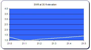
Manage your expectations. No two beams will produce the same SWR on any given band because SWR is determined by quite a number of factors such as height, length of feed line, proximate objects, and so forth. The SWR of a beam is not completely predictable. If your SWR is not 1.1:1, that does not mean there is a problem. The hexagonal beam should indicate SWR below 2:1 across all bands 10 – 20 meters except on the high end of 10 meters where the SWR can be expected to be above 2:1. Generally, you should get a dip in the SWR within the band even before it is raised to its operating height.  Notice the SWR curve in the blue chart at left. It drops down at around 21.1 mHz and then goes back up. This “drop” is what we mean by a dip. It is a low point where the SWR is lower than any other part of the range of frequencies you are looking at. If you are getting a dip, the chances are that everything with the hexagonal beam is OK. If SWR is above 2:1 or it does not dip for a band, then look for a problem.
Step two
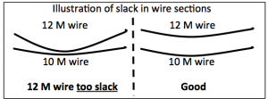
 Make a visual inspection. Are any wires of the hexagonal beam sagging so low as to touch or almost touch the wires below? If so, then the upper wire needs to have some slack taken out by moving a clip on the two front spreader arms out a little. Look at the junctions of wire and cord for each band. Are these located at about the same place on both sides of the beam? If not, then it might indicate that a wire or cord is cut incorrectly. It is not necessary for the beam to look perfect for it to work completely fine. But if a wire is cut to the wrong length, then that is a serious issue and must be resolved.
Step three
Remove all equipment from the feed line and make tests on the hexagonal beam from the bottom of the feed line to the antenna without any intervening equipment. If the problem disappears, then the hexagonal beam is fine and you should begin a process of finding what piece of equipment is causing the problem. If you still have a problem with the beam after isolating it from all devices such as switches, lightning arrestors, tuners and so forth, then it is time to think about bringing the antenna down for a closer look.
Step four
Lower the beam and remove the coax cable. Test the beam again for shorts and opens. Connect the SWR analyzer with a short piece of good cable to the beam and test the SWR. SWR will be higher when the beam is near the ground but you should be able to see a dip as you make tests across each band. If you do see the dip on each band, then the hex beam is working fine. Look for the problem in the cable and connectors. This would involve a step by step process to isolate the problem to a particular piece of equipment, cable or connector. (If you have a right angle connector in the line, remove it. These things are notoriously bad for their internal construction.)
If one or more bands do not show a dip, then check the length of the wires against the specifications in the assembly instructions. They should match within an inch. If they don’t contact us about a replacement. If you find a short or open, this should affect all bands and it is likely to be in the center post. For an open or short you can also check the soldered joint just inside the cap at the top of the center post. For a short you can remove one by one, the nuts and teflon insulators on the insulated terminals and look for small shards of aluminum that might have been left over from manufacture. If you do find any such short or open and cannot repair it yourself, call us for a replacement.
Perseverance is important in trouble shooting. Don’t give up. Be methodical but persistent and you will eventually pin point your problem.
The table below summarizes things to check when the hexbeam is not performing properly.
Troubleshooting Table
| Trouble Symptom | Likely problem (%) |
|---|---|
| Suddenly high SWR on all bands (SWR in excess of 3:1 at resonant freq.) | Feedline 95% -Check all coax conn. Sectionalize if possible (look for moisture, corrosion) Equipment 4% -Switches, tuner, radio Hexbeam center post 1% -Open or short -Check with tester from ground for short Must bring hexbeam down to check for open |
| Suddenly high SWR on one or two bands (SWR in excess of 3:1 at resonant freq.) | Broken wire -Visual inspection One wire hanging too close to wire below -In the “V” sections of the hexagon (Usually on 6, 10, 12M) |
| Noticeable increase in SWR during rain | This is normal. Permittivity of wires is changed by thin coating of water, shifting resonant frequency, temporarily. |
 KIO Technology
